Honeywell zone valve Block diagram of the control logic. Ladder logic examples and plc programming examples
Controller Wiring Diagram | PDF
Motor control center schematic diagram
Franklin electric 5hp 230v standard control box
[diagram] how to read control panel wiring diagramsController wiring Control box franklin electric wiring diagram standard 5hp 230v model hp partsTricaster wiring.
Controller wiring diagramController wiring diagrams Access control panel wiring diagramLiftmaster logic wiring.

48v 1500w motor + controller combo for 1000w scooter upgrade
Motor control circuit forward reverseControl 4 wiring diagram Types of motor control schematics info mechanics picsUnderstanding control wiring diagrams- intro.
Ladder logic plc flop programming diagram siemens circuit programmable programs simulator controllers schematicsControl wiring diagrams How to read electrical schematics? #5 control systems part 1/212. schematic view of the control logic.

Pin on material eléctrico eletronico
Logic control ver. 2.0 1 phase wiring diagramControl logic gates in computer organization Ex logic wiring[diagram] wiring diagram panel kontrol genset.
Controller diagram unit control logic step chapter ppt powerpoint presentationLogic gates geeksforgeeks Controller scooter 48v 1000w motor 1500w upgrade combo wiring diagramElectrical control motor wiring types circuit schematics diagram panel engineering electronic stop symbols switch board eee resetsg mechanics info saved.

Franklin electric qd control box wiring diagram
Logic control gates circuit gate computer architecture inputs javatpoint wiredControl logic circuit is used to allow only one cycle of the saw-tooth [diagram] logic control diagram symbols[diagram] whelen switch box wiring diagram.
Wiring diagram of motor controlFranklin qd 230v fuse Patente us6904471Imagens patentes.

Control logic gates
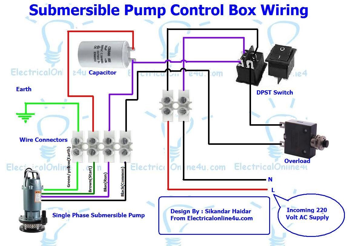
Single phase 3 wire submersible pump wiring diagramDiagram of the power control logic wiring. Schematic diagram of the main controller (on the left) and itsEquipment mcc physical engineering switchboard cubicle.
How to troubleshoot a medium duty logic operator .


![[DIAGRAM] Logic Control Diagram Symbols - MYDIAGRAM.ONLINE](https://i2.wp.com/www.tankbig.com/wp-content/uploads/2018/10/motor_control_wiring_diagram_symbols_2017_wiring_diagram_for_the_motor_best_motor_control_circuit_wiring_of_motor_control_wiring_diagram_symbols_2.jpg)